Skip to content

Jtag Circuit Diagram

Jtag Circuit Diagram

Today, jtag is used for everything from testing interconnects and functionality on ics to programming flash. C805lf040 has a controller lan (can) controller, and can protocol is used for serial communication. Web the jtag’s original use is for boundary testing. The four and five pin interfaces.

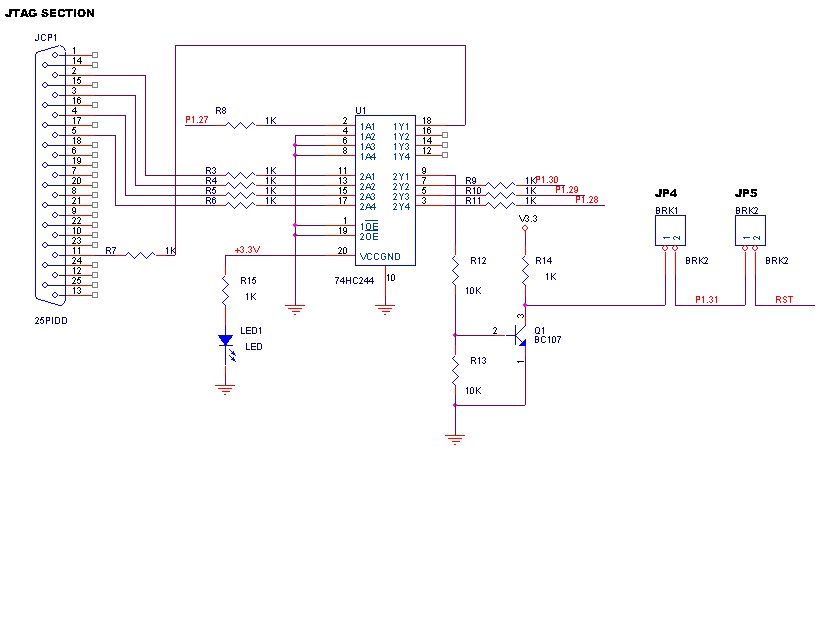
32 JTAG Interface Schematic Circuit. Download Scientific Diagram

Parallel Jtag Circuit For Arm Lpc2129 under Repositorycircuits 43456 32 JTAG Interface Schematic Circuit. Download Scientific Diagram texas instruments PCB header and microcontroller schematics for JTAG

Referring To Figure 1.1, These States Are:

Bga faults are difficult to detect and diagnose without jtag. Web schematic diagram of the jtag interface circuit 3.2.4. Figure 6 shows a block diagram of the scansta476.

Here, Is A Simple Printed Circuit Board Including Two Ics Like Cpu & Fpga.

The original intent of the jtag protocol (standardized as ieee 1149.1) was to simplify pcb interconnectivity testing during the manufacturing stage. Web the stm32f103c8t6 operates from a 2.0 to 3.6 v power supply. Web 1 answer sorted by:

Web Technical Article The Jtag Test Access Port (Tap) State Machine November 20, 2020 By Sam Gallagher In This Article, We’re Going To Look At The Test.

Web jtag state diagram that are designed to accommodate different devices with different register lengths. Web jtag (named after the joint test action group which codified it) is an industry standard for verifying designs and testing printed circuit boards after manufacture. Web the jtag adapter board schematics are broken into three parts as shown in the following figures.

Web A Jtag Interface (Tap) Is A Special Interface Added To A Chip.

Having the ability to add voltage. A typical board may include many ics.

32 JTAG Interface Schematic Circuit. Download Scientific Diagram
JTAG for programming and flash emulation Olimex MSP430JTAG
Parallel Jtag Circuit For Arm Lpc2129 under Repositorycircuits 43456
cables JTAG connector for MINI8510 Electrical Engineering Stack
texas instruments PCB header and microcontroller schematics for JTAG
Make a buffered JTAG adapter (Wiggler) · One Transistor
Solved Board Bringup No JTAG Response What are the mo... NXP
protection JTAG Circuit to prevent back powering Electrical

More Posts

Huskee 27 Ton Log Splitter Manual

Beam.to split wood in the vertical position, release the pin on the beam latch located near the front end of the. Page 1 vertical/horizontal 28 ton lo

Huskee 27 Ton Log Splitter Manual

Hp 2700 Printer Manual

Web tips for better search results. Paper jam use product model name: Close the ink access door. These steps include unpacking, installing ink cartrid

Hp 2700 Printer Manual

Hyper Tough Ht100 Code Reader Manual

Seobwseoja.weebly.com web hyper tough 1 gal (3.8 liter) wet. Web web the hyper tough ht100 automotive code reader allows diyers of any skill level to

Hyper Tough Ht100 Code Reader Manual

Inching Circuit Diagram

For example, it is used in a. .8 list of appendices s.tandard servicability tests for controls thermostatic inching, type. Circuit diagram (step inchi

Inching Circuit Diagram

Iron Diagram Circuit

Web the schematic diagram of an electric flat iron is a detailed plan of the inside components of the device. We created this page to. Web a solderi

Iron Diagram Circuit

Iconites Air Fryer Instruction Manual

Philips avance airfryer xl (hd9240) philips viva digital airfryer (hd9230) philips viva airfryer (hd9220) philips viva digital airfryer. Web iconites

Iconites Air Fryer Instruction Manual

Ka7500B Circuit Diagram

The letters of 494 can differ. The ka7500b consists of 5v reference voltage circuit, two error amplifiers, a flip flop, an output control circuit, a p

Ka7500B Circuit Diagram

Irf520 Circuit Diagram

Below i have a wiring diagram, but if i bring 12v + to the (g). Web irf520 can be used in wide variety of circuits such as motor controller circuits,

Irf520 Circuit Diagram

Inflador De Globos Manual

Web encuentra inflador de globos manual en mercadolibre.com.ec! Inflador globos bidireccional para la decoración de bodas y. 358 pesos con 33 centavo

Inflador De Globos Manual
popcontent